How to Size a Wastewater Pump for Commercial and Municipal Applications
An undersized wastewater pump can’t keep up with peak demand, leading to wet well overflow and regulatory violations. An oversized one cycles too frequently, wearing out motor components and consuming far more energy than necessary. Getting the sizing right — and understanding how to size a wastewater pump from first principles — is the foundational step in any successful lift station or force main design.
Wastewater pump sizing is the process of matching a pump’s flow rate and pressure output to the specific hydraulic demands of a system — accounting for the volume of wastewater generated, the elevation it must be lifted, the friction it encounters in the piping, and the operational and regulatory requirements of the application. Miss any one of these variables and the pump selection will be wrong, regardless of how reputable the brand. Here is the complete sizing process for commercial and municipal applications.
Wastewater Pump Sizing Starts with an Accurate Flow Rate Calculation
Flow rate — expressed in gallons per minute (GPM) or gallons per day (GPD) — represents how much wastewater the pump must move. It is the first and most consequential variable in the sizing process, because every downstream calculation depends on it. Underestimating peak flow is the single most common cause of undersized pump installations.
Flow Rate for Commercial Applications
For commercial wastewater systems — restaurants, hotels, office buildings, industrial facilities — peak flow rate is typically calculated using the fixture unit method defined in the Uniform Plumbing Code (UPC) or International Plumbing Code (IPC). The process involves:
- Counting all plumbing fixtures in the facility (toilets, urinals, sinks, floor drains, dishwashers, etc.)
- Assigning fixture unit values to each based on code tables
- Converting total fixture units to a peak GPM using the Hunter’s Curve or equivalent flow conversion table
- Applying a peak demand factor based on facility type and occupancy patterns (a restaurant at lunch service peaks very differently than an office building)
- Adding any process wastewater flows from manufacturing, food service, or industrial operations that run independently of plumbing fixtures
For facilities with highly variable or intermittent flows — commercial kitchens, car washes, laundromats — metered flow data from a comparable facility is more reliable than fixture unit estimates alone. When in doubt, size for the credible worst case rather than the average.
Flow Rate for Municipal Applications
Municipal wastewater system sizing follows a different methodology based on population served, per-capita flow rates, and infiltration and inflow (I/I) allowances:
- Average daily flow (ADF): Estimated using per-capita generation rates — typically 100 to 120 gallons per person per day for residential areas, adjusted for commercial and industrial contributions in the service area
- Peak hourly flow: The ADF multiplied by a peaking factor — commonly 2.5 to 4.0 for smaller systems, lower for larger service areas — to account for morning and evening demand peaks
- Infiltration and inflow allowance: Added to account for groundwater infiltrating through pipe joints and storm-related inflow events; typically 100 to 500 gallons per day per inch-diameter per mile of sewer, depending on pipe condition
- Future growth projection: Municipal pump stations are sized for a design horizon of 20 to 50 years, requiring flow projections that account for planned development in the service area
The design flow rate used for pump sizing is typically the peak hourly flow — the highest flow the pump must handle during normal operations — not the average daily flow. Designing to average flow produces a system that regularly surcharges during peak periods.
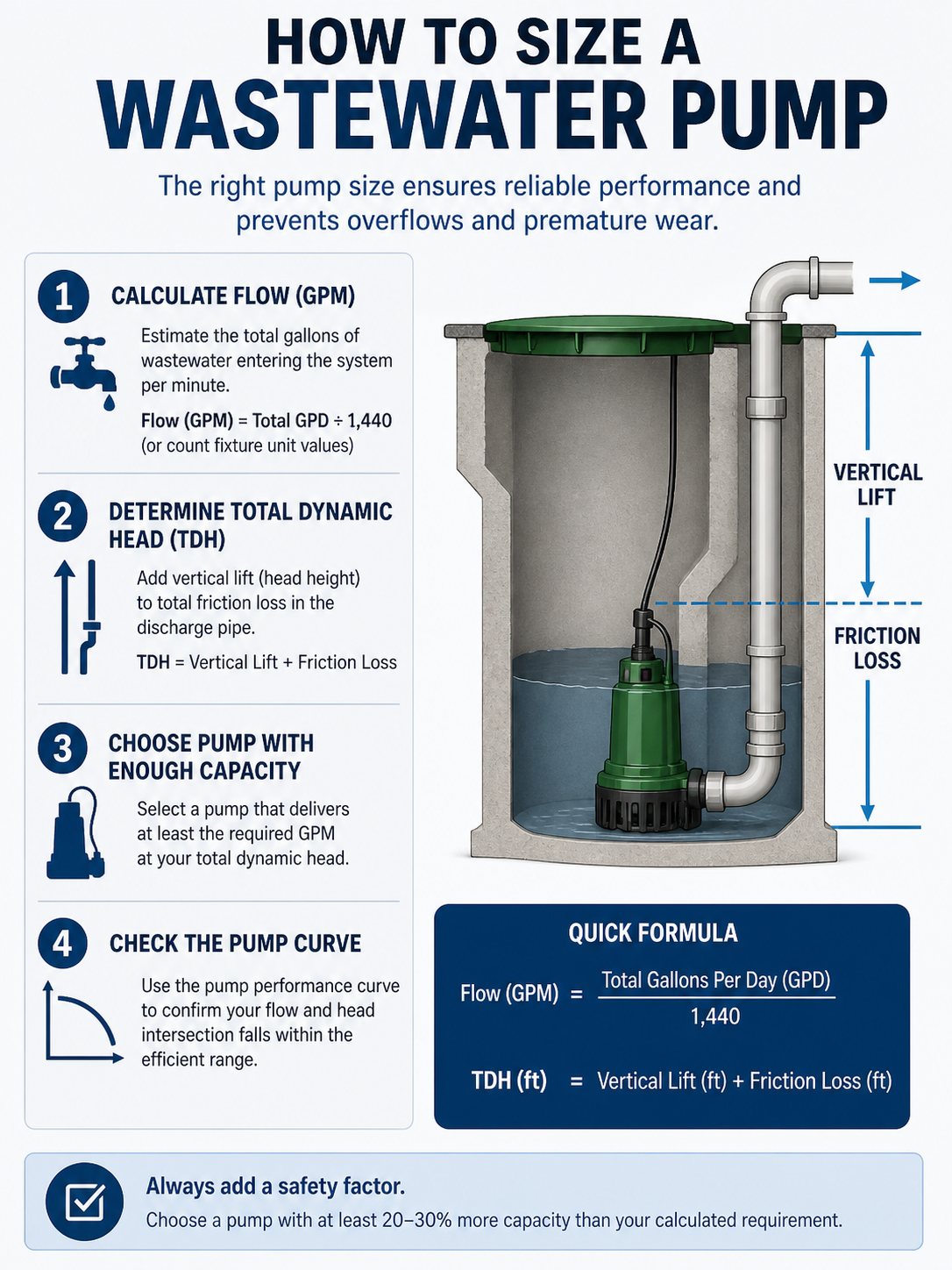
Total Dynamic Head Determines the Pressure the Pump Must Overcome
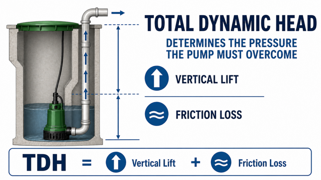
Once flow rate is established, the second critical variable is Total Dynamic Head (TDH) — the total pressure the pump must generate to move wastewater from the wet well to the discharge point. TDH is expressed in feet of head (or PSI, where 1 PSI ≈ 2.31 feet of head) and is the sum of four components.
Static Head
Static head is the vertical elevation difference between the water surface in the wet well at its lowest operating level and the centerline of the discharge pipe at the highest point in the system — typically the point where the force main discharges into a gravity sewer or treatment facility. This is the fixed, elevation-based component of TDH and is calculated directly from site survey data.
Friction Head Losses
As wastewater flows through the force main, friction between the fluid and pipe walls consumes pressure. Friction head is calculated using the Hazen-Williams equation (most common for wastewater piping) or the Darcy-Weisbach equation:
- Pipe material and roughness coefficient (C-factor): PVC typically uses C = 150; ductile iron uses C = 130 to 140
- Pipe inside diameter — friction losses increase dramatically as diameter decreases
- Flow velocity — friction losses increase with the square of velocity; target 2 to 8 ft/sec for wastewater force mains to prevent solids settling and excessive wear
- Total pipe length from pump to discharge point
Minor Losses
Check valves, gate valves, elbows, tees, and other fittings all introduce additional head losses beyond straight pipe friction. These are calculated using loss coefficients (K-values) for each fitting type and are expressed as equivalent feet of straight pipe. In systems with short force mains or numerous fittings, minor losses can represent a significant percentage of total TDH and should not be estimated or rounded away.
Pressure Head at Discharge
If the force main discharges into a pressurized system — such as a pressurized sewer main or a treatment plant header — the backpressure at the discharge point must be added to TDH. In gravity discharge systems, this component is typically zero.
Total Dynamic Head = Static Head + Friction Head + Minor Losses + Discharge Pressure Head. This is the TDH value used to select the pump from a manufacturer’s performance curve.
How Do You Select the Right Pump Type for a Wastewater Application?
With flow rate and TDH established, the next step is identifying which pump type is appropriate for the application. Wastewater systems involve fluids with suspended solids, rags, and organic material — considerations that immediately narrow the field from general pump categories.
Submersible vs. Dry Pit Pumps
The majority of modern municipal and commercial lift stations use submersible pumps, which are installed directly in the wet well below the water surface. Submersible installations eliminate the need for a separate pump room, reduce installation costs, and simplify maintenance access in smaller stations. Dry pit pumps — installed above the wet well in a dedicated pump room — remain common in larger municipal stations where extended service intervals and higher motor power requirements make accessible above-grade installation preferable.
Centrifugal vs. Grinder Pumps
Most commercial and municipal wastewater applications use centrifugal pumps with non-clog impellers — specifically designed to pass solids up to a defined diameter (typically 3 inches for municipal applications) without clogging. Grinder pumps use a cutting mechanism to macerate solids before pumping, and are most appropriate for low-pressure sewer (LPS) systems serving individual residences or small commercial connections where gravity flow to a wet well is not feasible. Grinder pumps are not a substitute for non-clog centrifugal pumps in high-flow applications.
Solids Handling and Impeller Design
For wastewater applications, specify the maximum solids-passing diameter required — a function of the solids content expected in the waste stream. Municipal wastewater typically requires a minimum 3-inch solids passage. Key impeller types include:
- Single-vane (semi-open) impellers: Maximum solids passage, lower efficiency, best for high-solids municipal applications
- Dual-vane impellers: Balance of solids handling and hydraulic efficiency, common in mid-range municipal lift stations
- Closed impellers: Highest efficiency but reduced solids handling — best for screened or treated effluent rather than raw wastewater
- Vortex impellers: The solids never contact the impeller; ideal for applications with stringy or fibrous material but lowest hydraulic efficiency of the group
Reading a Pump Performance Curve Confirms the Right Selection
Once candidate pumps are identified, the final confirmation step is overlaying the system curve with the pump performance curve to verify the operating point. This step is non-negotiable — a pump that produces the right flow at a different head than your system requires will not operate at the calculated design point in the field.
The system curve is a plot of required head versus flow rate for your specific piping system. At zero flow, the required head equals static head only. As flow increases, friction losses increase with the square of velocity, causing the system curve to rise steeply. The pump curve is the manufacturer’s published plot of head versus flow for that pump at a given speed and impeller diameter — typically showing a declining head as flow increases.
The operating point is where these two curves intersect. For a properly sized pump:
- The operating point should fall within the pump’s preferred operating region (POR) — typically between 70 and 120 percent of the best efficiency point (BEP) flow
- Operating significantly left of BEP (low flow, high head) causes recirculation, vibration, and accelerated wear
- Operating significantly right of BEP (high flow, low head) overloads the motor and reduces pump life
- If the operating point falls outside the POR, adjust pipe diameter, impeller trim, or select a different pump model
At Pump Professionals, our team performs pump curve analysis as part of the selection process — ensuring that the pump we recommend actually operates at the design point in your system, not just on paper.
What Else Should You Consider Before Finalizing a Wastewater Pump Selection?
Flow rate, TDH, pump type, and operating point are the core sizing variables — but a complete pump selection for commercial or municipal applications also requires addressing several additional factors that directly affect long-term reliability and regulatory compliance.
- Redundancy (N+1): Municipal lift stations almost universally require a standby pump capable of handling peak flow independently. Most state environmental agencies mandate N+1 redundancy as a condition of operating permits. Commercial applications with continuous operations or no overflow tolerance should be evaluated for standby pump requirements as well.
- Motor sizing and efficiency: The motor must be sized to handle the maximum power demand across the full operating range of the pump — not just at the design point. For variable flow applications, variable frequency drives (VFDs) provide significant energy savings by matching pump speed to actual demand rather than running at full speed continuously.
- Wet well sizing: The wet well must provide sufficient volume between the pump-on and pump-off levels to limit motor starts per hour to the manufacturer’s maximum — typically 6 to 10 starts per hour for submersible pumps. Excessive cycling is a leading cause of premature motor failure.
- Material selection: Cast iron is standard for most wastewater pump casings and impellers. Stainless steel components are specified for corrosive or high-sulfide environments. Seals and wear rings should be specified for the specific fluid chemistry of the application.
- Local codes and regulatory requirements: State environmental agencies, local utilities, and municipal engineering standards often specify minimum pump requirements, alarm systems, level controls, and emergency overflow provisions. Confirm applicable standards before finalizing equipment specifications.
Frequently Asked Questions About Wastewater Pump Sizing
What is the most common mistake in wastewater pump sizing?
Underestimating peak flow rate is the most frequent sizing error — particularly in commercial applications where fixture unit calculations don’t account for simultaneous use factors or process flows, and in municipal systems where infiltration and inflow are underestimated. The result is a pump that can’t handle peak demand, leading to wet well surcharging, overflows, and permit violations. Always size for peak hourly flow with appropriate safety margins, not average daily flow.
What is a reasonable target velocity for a wastewater force main?
Most wastewater engineering standards target a minimum velocity of 2 feet per second to prevent solids settling in the force main, and a maximum of 8 to 10 feet per second to limit pipe wear and water hammer risk. The sweet spot for most municipal force mains is 3 to 6 feet per second at design flow. If your flow rate produces velocities outside this range in your selected pipe size, adjust the pipe diameter before finalizing the pump selection.
When should a grinder pump be used instead of a non-clog centrifugal pump?
Grinder pumps are appropriate for individual service connections in low-pressure sewer systems — typically single-family residences or small commercial buildings that cannot drain by gravity to a wet well. They are not a substitute for non-clog centrifugal pumps in lift stations handling combined flow from multiple sources. Using a grinder pump in a high-flow application dramatically increases maintenance frequency and operating costs.
How do variable frequency drives affect wastewater pump sizing?
A variable frequency drive (VFD) allows the pump to operate across a range of speeds rather than at fixed full speed, matching output to actual inflow rather than cycling on and off. VFDs reduce energy consumption, limit motor starts, and extend pump and motor life in applications with variable inflow. When sizing a pump for VFD operation, verify that the pump’s operating range across all expected speeds remains within the preferred operating region — a pump that performs well at full speed may cavitate or recirculate at reduced speeds if not specifically evaluated for variable-speed operation.
Can Pump Professionals help with wastewater pump sizing and selection?
Yes. Pump Professionals provides expert guidance on pump sizing and selection for commercial, municipal, and industrial wastewater applications. Our team works with municipalities, mechanical contractors, plumbers, and builders to identify the right pump for the specific hydraulic demands of each project — including pump curve analysis, redundancy planning, and coordination with brands like Homa Pumps and Liberty Pumps. Call us at (317) 674-3819 or request a quote online to discuss your application.
Accurate Sizing Upfront Prevents Costly Problems Downstream
Wastewater pump sizing is a discipline where the consequences of errors show up slowly at first — slightly elevated energy bills, more frequent cycling, earlier-than-expected maintenance — and then all at once when a pump fails during a peak demand event. Taking the time to calculate flow rate accurately, build a complete TDH model, verify the operating point on the pump curve, and address redundancy and controls requirements is what separates a system that performs reliably for 20 years from one that causes problems within the first few.
At Pump Professionals, we combine deep product knowledge across leading wastewater pump brands with the technical expertise to help you size and select the right equipment for your specific application — whether you’re designing a new municipal lift station, upgrading a commercial force main, or replacing a pump that’s been undersized from the start. Call (317) 674-3819 or request a quote online and let our team help you get the sizing right the first time.